Media
Image
Media Name
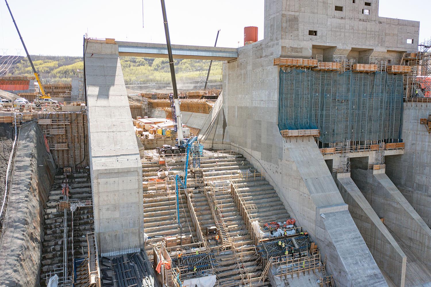
The auxiliary (passive) spillway operates without electricity and can safely manage flows that would otherwise pass through the mechanical spillways. | May 2023
Caption
The auxiliary (passive) spillway operates without electricity and can safely manage flows that would otherwise pass through the mechanical spillways. | May 2023
Media
Image
Media Name
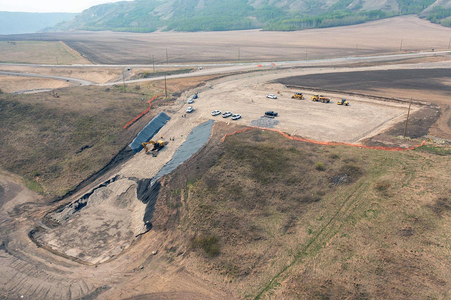
The Halfway River boat launch and day use area. | May 2023
Caption
The Halfway River boat launch and day use area. | May 2023
Media
Image
Media Name
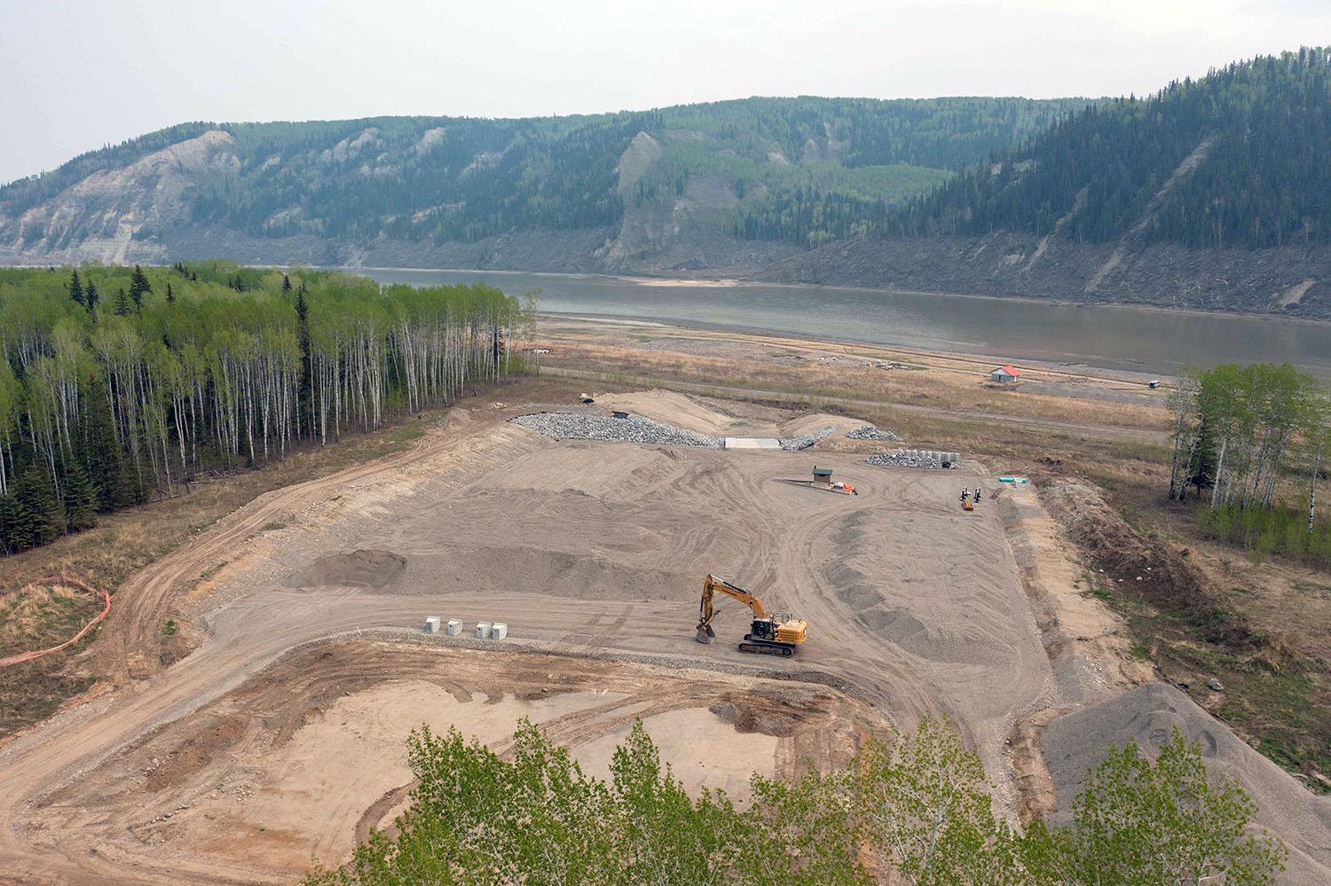
The Lynx Creek boat launch and day use area. | May 2023
Caption
The Lynx Creek boat launch and day use area. | May 2023
Media
Image
Media Name
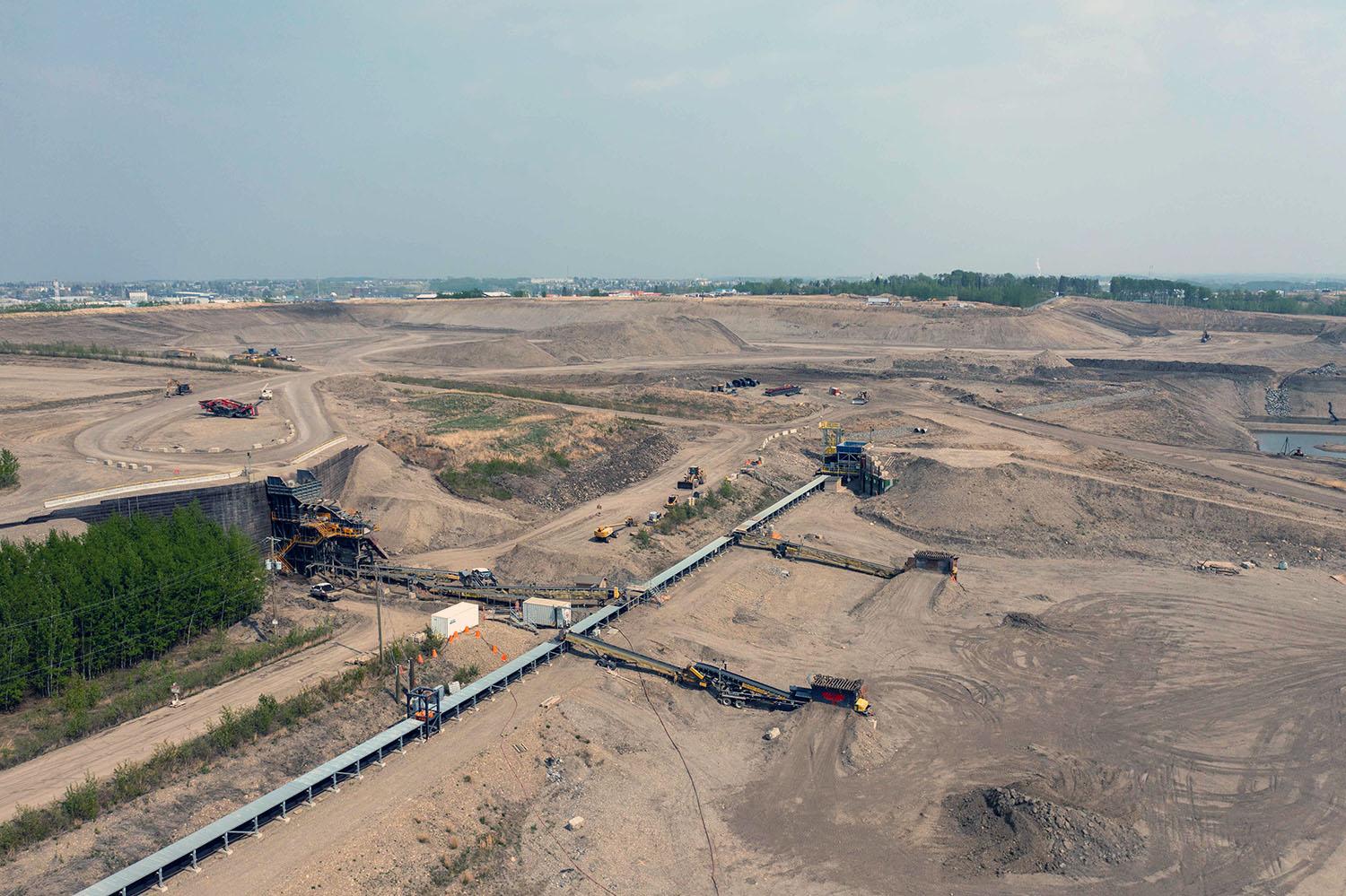
The glacial till used to build the dam comes from the 85th Avenue Industrial Lands. A five-kilometre-long conveyor belt transports the material to the dam site. | May 2023
Caption
The glacial till used to build the dam comes from the 85th Avenue Industrial Lands. A five-kilometre-long conveyor belt transports the material to the dam site. | May 2023
Media
Image
Media Name
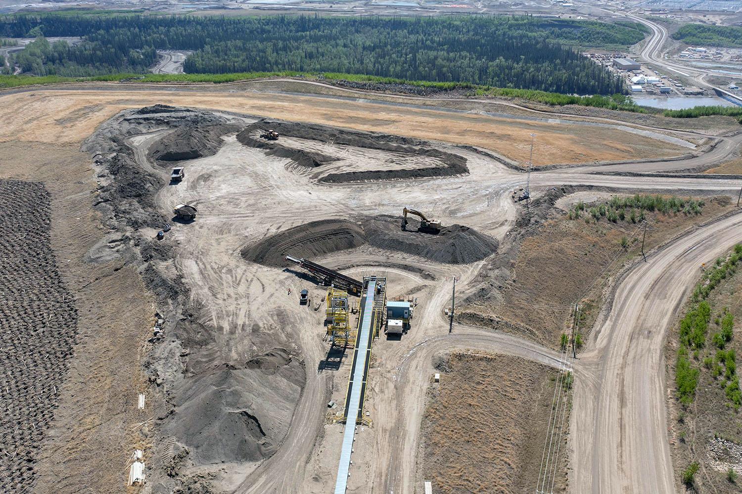
The conveyor belt moves glacial till to a stockpile area on the construction site, where trucks then haul it to the dam core. | May 2023
Caption
The conveyor belt moves glacial till to a stockpile area on the construction site, where trucks then haul it to the dam core. | May 2023
Media
Image

Media Name
Fish habitat areas are developed below the Site C dam by creating new channels and making the main river channel deeper to provide places for fish to feed and rest. | May 2023
Caption
Fish habitat areas are developed below the Site C dam by creating new channels and making the main river channel deeper to provide places for fish to feed and rest. | May 2023
Media
Image
Media Name
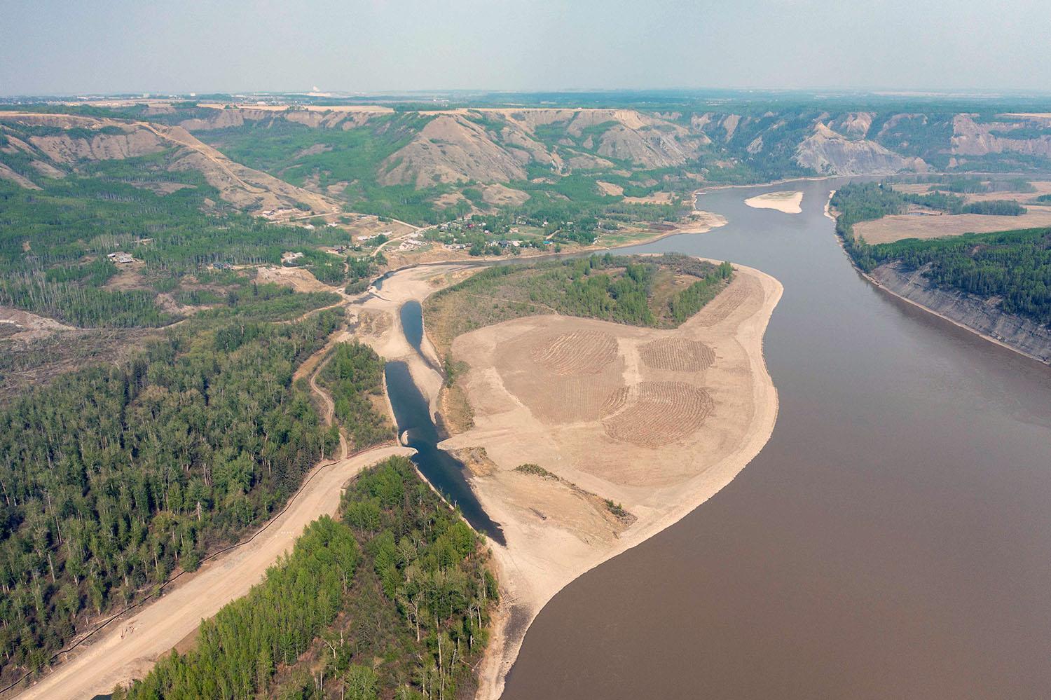
A completed fish habitat enhancement project four kilometres downstream of the Site C dam. The riverbed at the shoreline has been deepened to prevent fish from stranding in shallow water. | May 2023
Caption
A completed fish habitat enhancement project four kilometres downstream of the Site C dam. The riverbed at the shoreline has been deepened to prevent fish from stranding in shallow water. | May 2023
Media
Image
Media Name
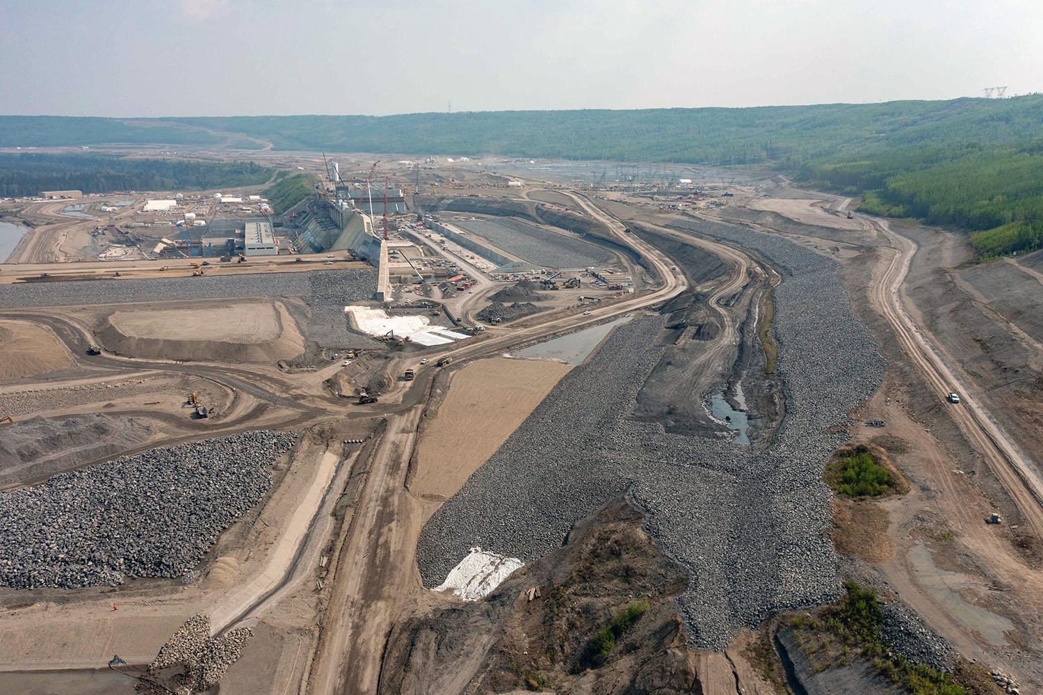
Downstream view of the approach channel. Water from the reservoir flows into the channel where it enters the intakes and drops down the penstocks into the turbine units and generates electricity. | May 2023
Caption
Downstream view of the approach channel. Water from the reservoir flows into the channel where it enters the intakes and drops down the penstocks into the turbine units and generates electricity. | May 2023
Media
Image
Media Name
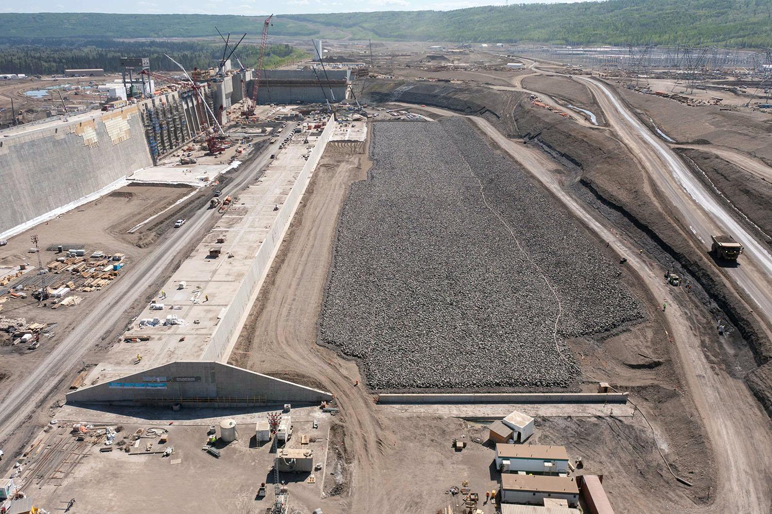
Downstream view of the approach channel. Water will flow from the reservoir into the channel, towards the intakes and spillways. | May 2023
Caption
Downstream view of the approach channel. Water will flow from the reservoir into the channel, towards the intakes and spillways. | May 2023
Media
Image
Media Name
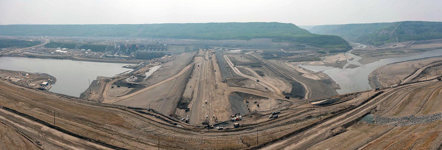
South-facing view over the dam where layers of glacial till are compacted to reach the final elevation of 60 metres above the riverbank. | May 2023
Caption
South-facing view over the dam where layers of glacial till are compacted to reach the final elevation of 60 metres above the riverbank. | May 2023
Media
Image
Media Name
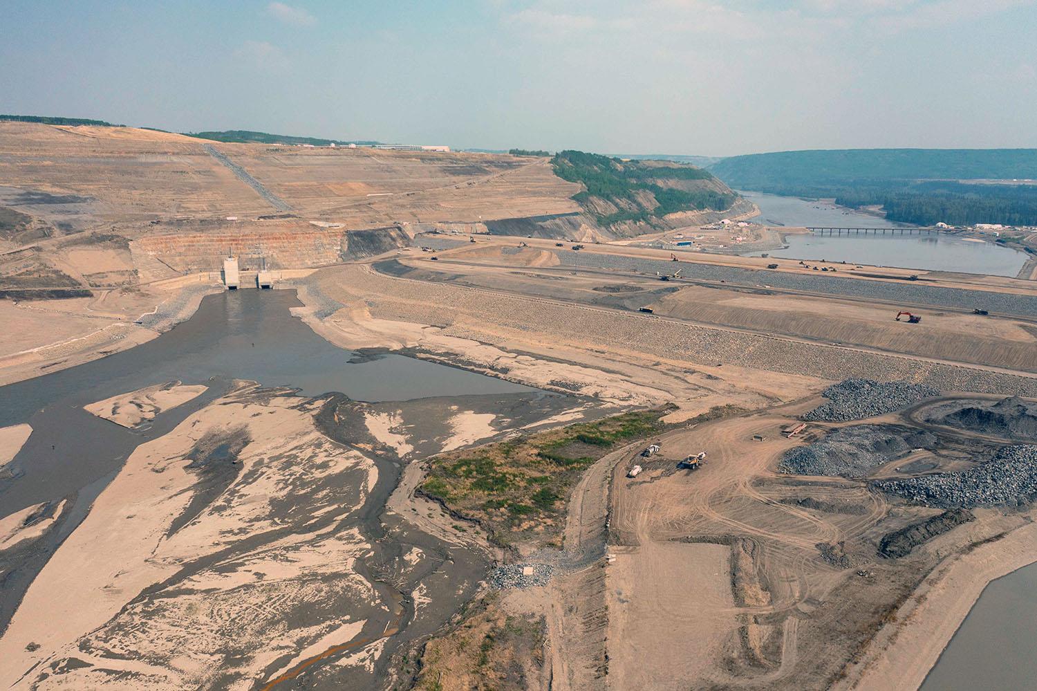
Upstream view of the dam, with the diversion tunnel inlets on the left. | May 2023
Caption
Upstream view of the dam, with the diversion tunnel inlets on the left. | May 2023
Media
Image
Media Name
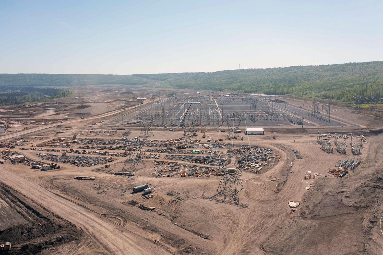
The 500-kilovolt transmission towers are installed in the substation and ready to be connected to the generating station. | May 2023
Caption
The 500-kilovolt transmission towers are installed in the substation and ready to be connected to the generating station. | May 2023
Media
Image
Media Name
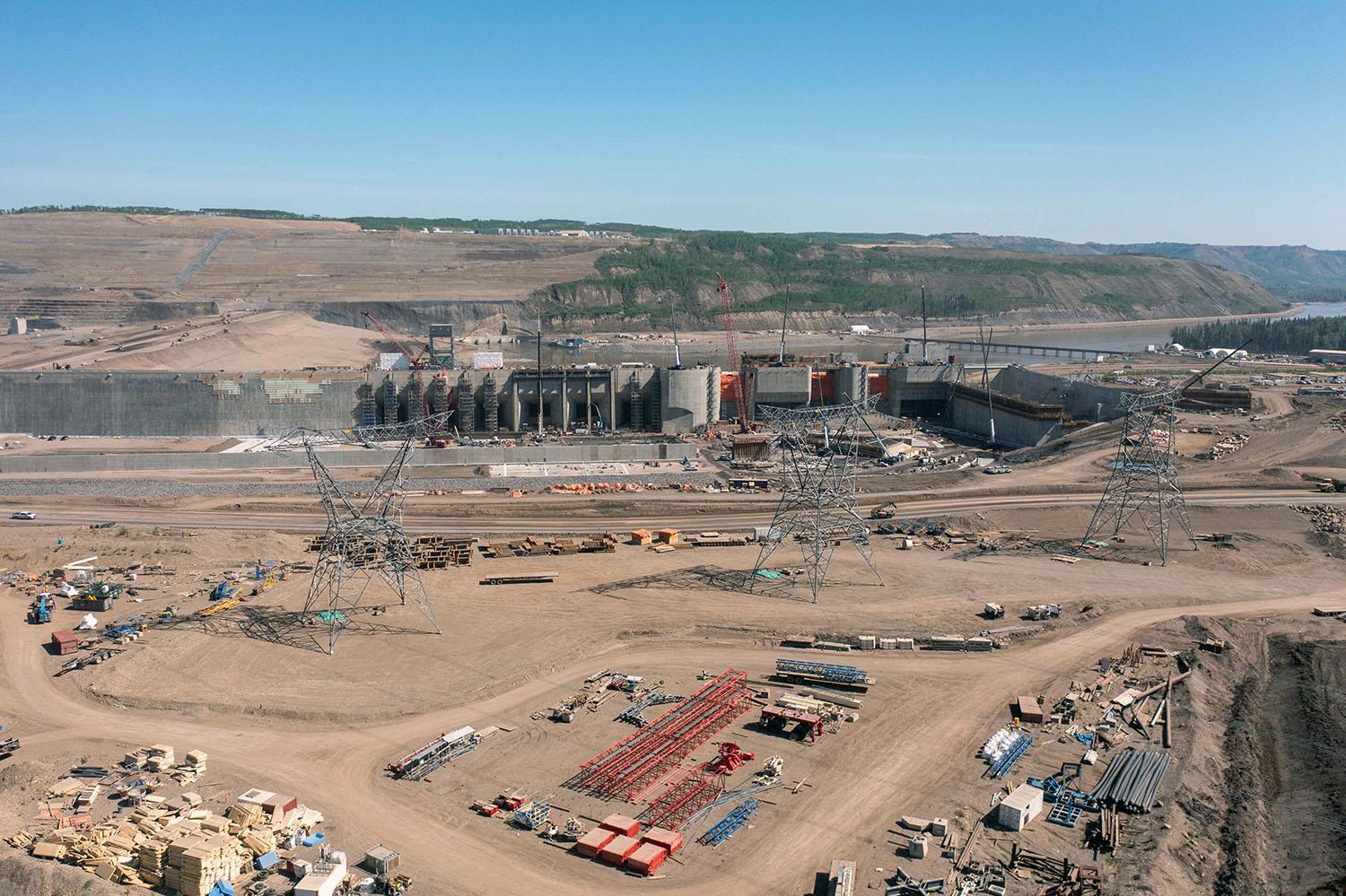
North-facing view of the three 500-kilovolt transmission towers that will connect to the dam to transport electricity into the BC Hydro transmission system. | May 2023
Caption
North-facing view of the three 500-kilovolt transmission towers that will connect to the dam to transport electricity into the BC Hydro transmission system. | May 2023
Media
Image

Media Name
From left centre the dam buttress, intakes, mechanical spillways, the auxiliary spillway, and the spillway end-wall. | May 2023
Caption
From left centre the dam buttress, intakes, mechanical spillways, the auxiliary spillway, and the spillway end-wall. | May 2023
Media
Image
Media Name
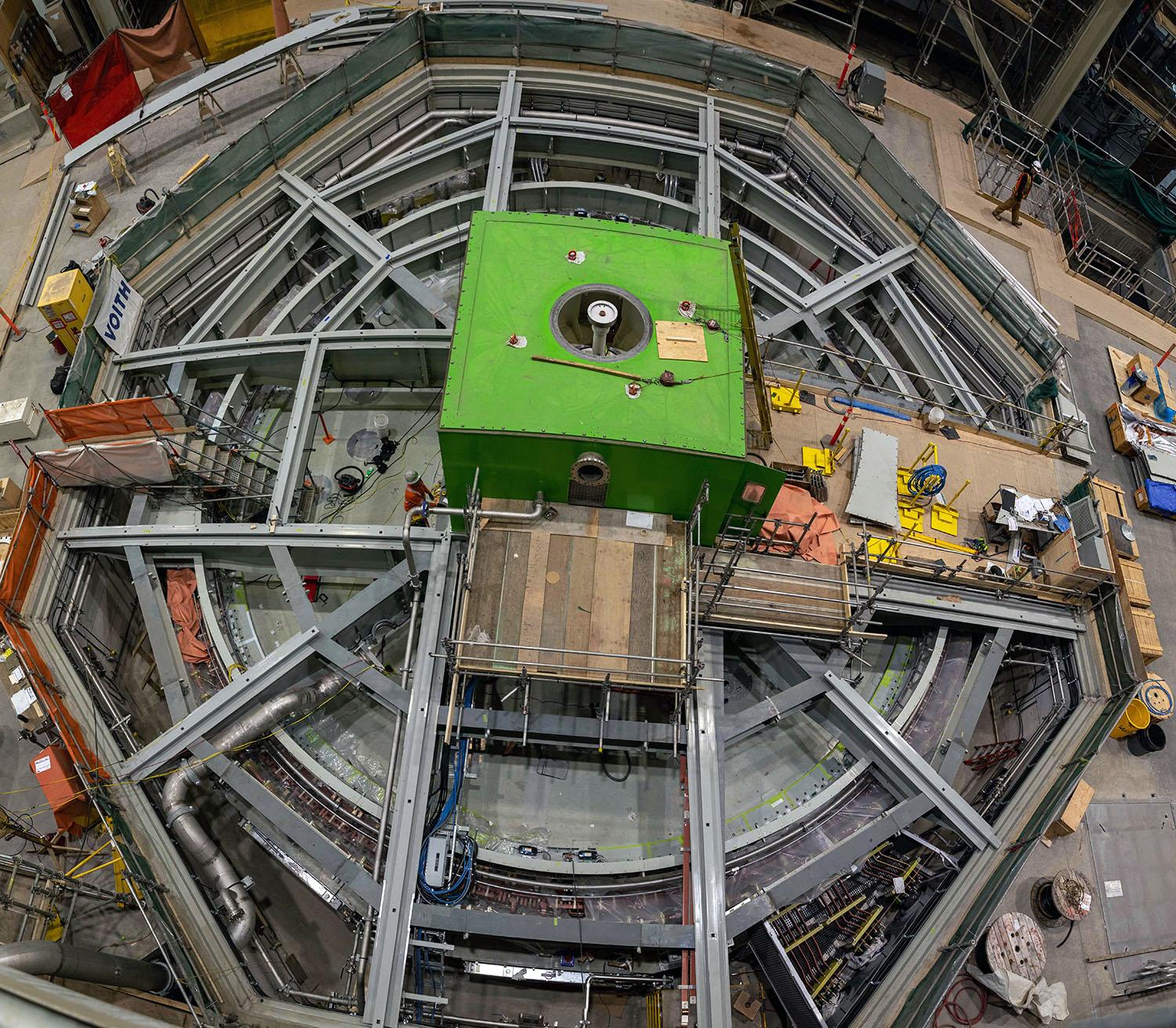
The green box is the housing for the brush gears. Preparing for top cover installation on the upper bracket for turbine unit 1. | May 2023
Caption
The green box is the housing for the brush gears. Preparing for top cover installation on the upper bracket for turbine unit 1. | May 2023
Media
Image
Media Name
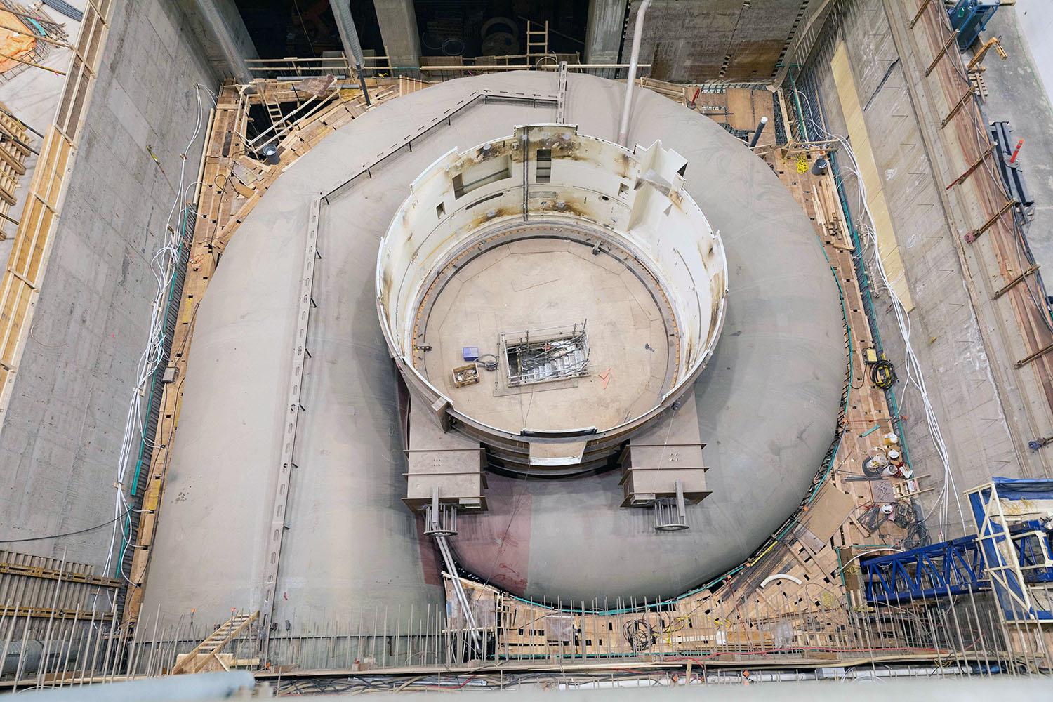
Turbine unit 6 is ready to be embedded in concrete. A plywood deck has been placed on the reinforcing steel to allow the workers to place the concrete. | May 2023
Caption
Turbine unit 6 is ready to be embedded in concrete. A plywood deck has been placed on the reinforcing steel to allow the workers to place the concrete. | May 2023
Media
Image

Media Name
A mechanically-stabilized earth wall is being built on the east end of the auxiliary spillway. | May 2023
Caption
A mechanically-stabilized earth wall is being built on the east end of the auxiliary spillway. | May 2023
Media
Image
Media Name
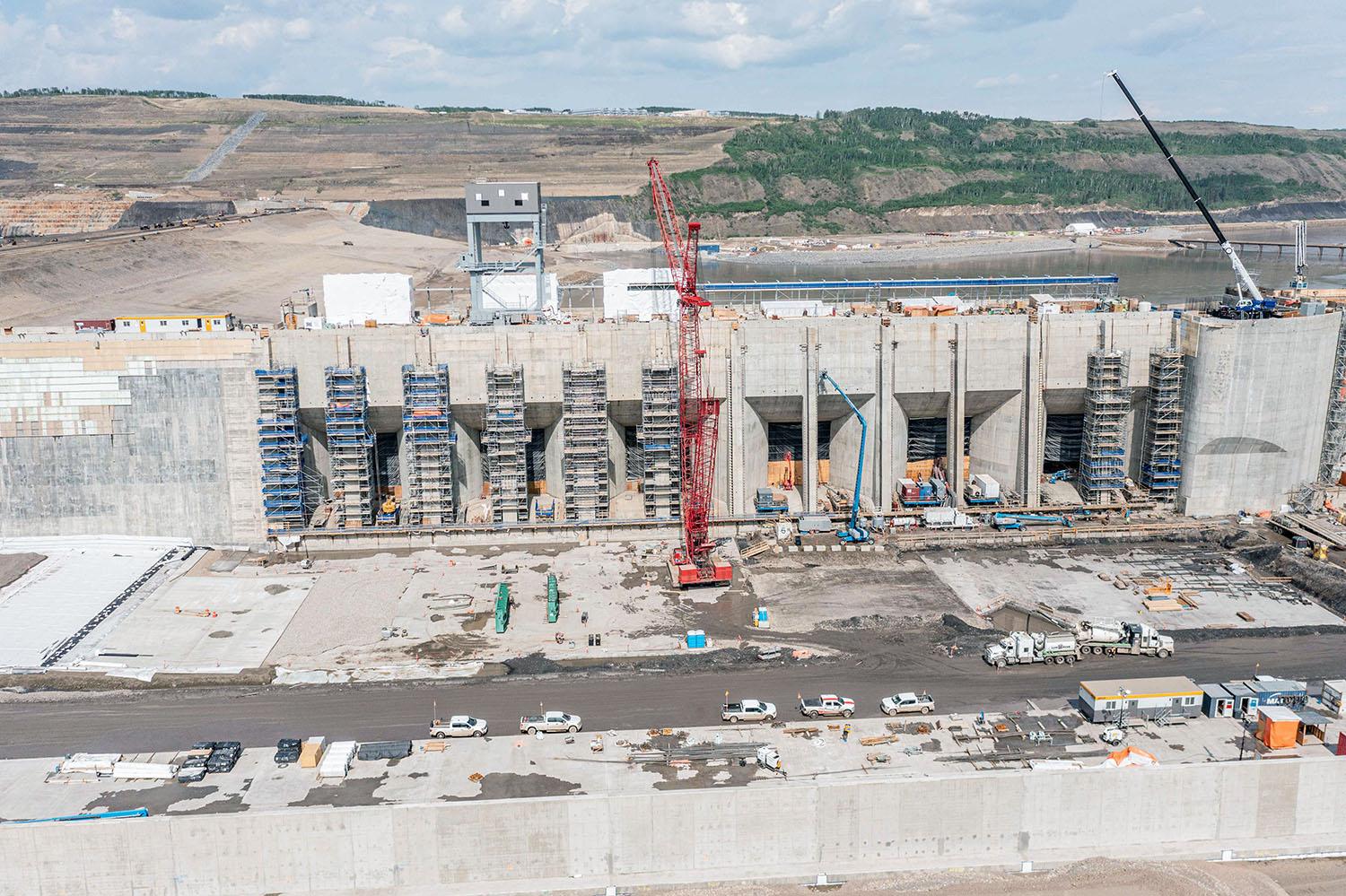
Installing trash rack guides on units four and five. Trash racks, or debris screens, stop material from entering the intakes and damaging the turbine units. | May 2023
Caption
Installing trash rack guides on units four and five. Trash racks, or debris screens, stop material from entering the intakes and damaging the turbine units. | May 2023
Media
Image
Media Name
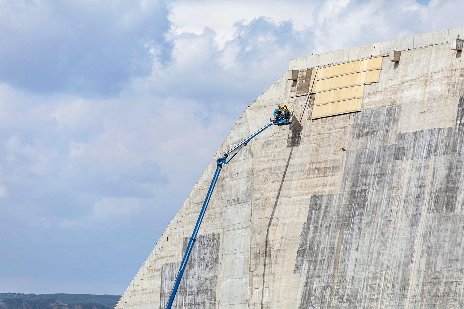
The remaining few panels used to cure the roller compacted concrete are removed from the buttress. | May 2023
Caption
The remaining few panels used to cure the roller compacted concrete are removed from the buttress. | May 2023
Media
Image
Media Name
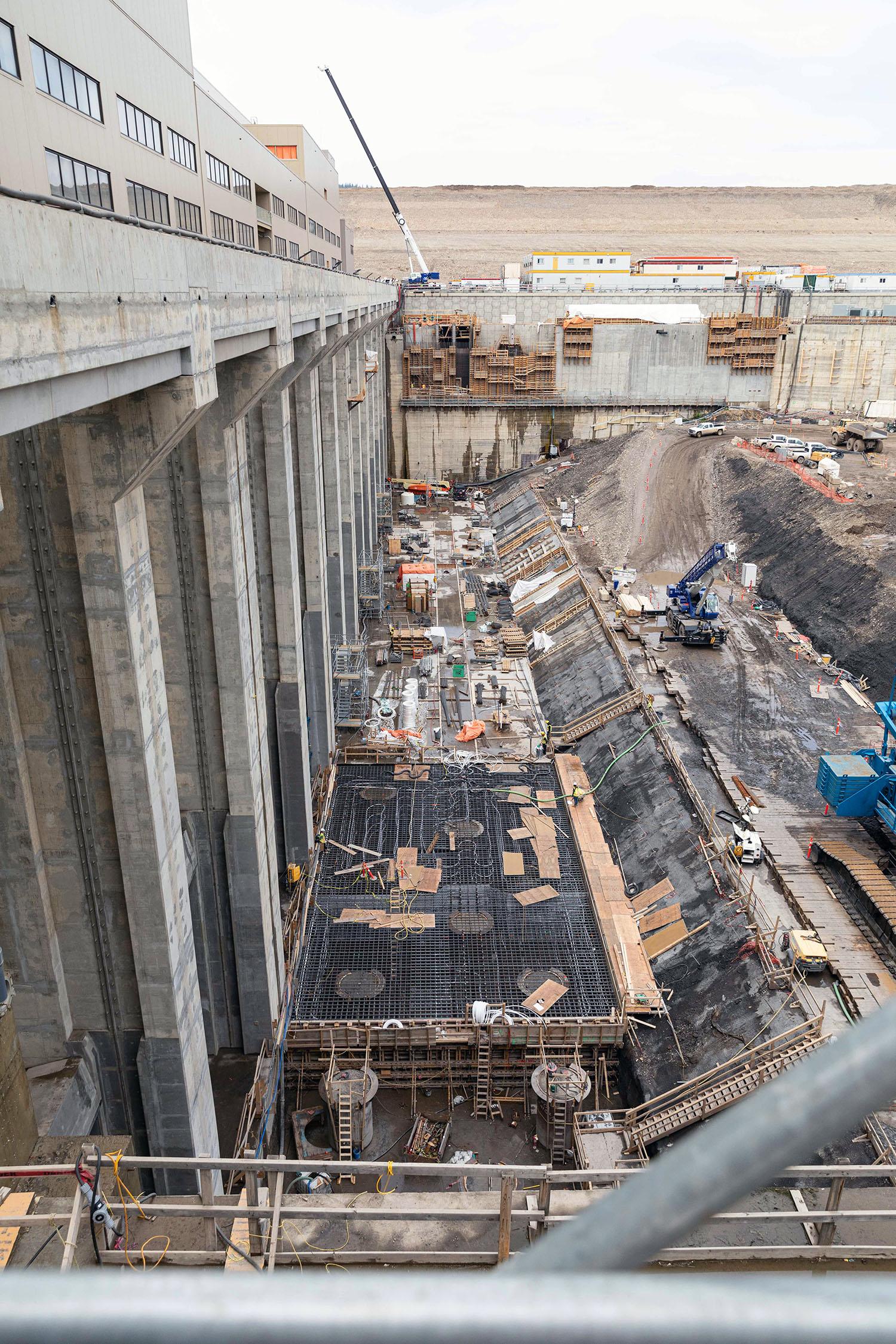
The tailrace is where the water exits the dam. The water has travelled from the reservoir through the approach channel into the intakes and down the penstocks into the six turbine runners to generate electricity. | May 2023
Caption
The tailrace is where the water exits the dam. The water has travelled from the reservoir through the approach channel into the intakes and down the penstocks into the six turbine runners to generate electricity. | May 2023
Media
Image
Media Name
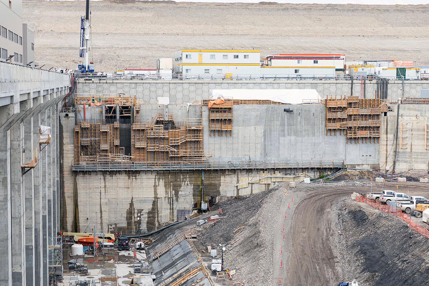
Fish travelling up the Peace River will travel through the permanent upstream fish passage facility. Migrating fish will be sorted, tagged, and released past the damsite into the reservoir. | May 2023
Caption
Fish travelling up the Peace River will travel through the permanent upstream fish passage facility. Migrating fish will be sorted, tagged, and released past the damsite into the reservoir. | May 2023
Media
Image

Media Name
Northwest-facing view of the approach channel where water will flow from the reservoir into each of the six intake units to deliver water to the turbine units to generate electricity. | May 2023
Caption
Northwest-facing view of the approach channel where water will flow from the reservoir into each of the six intake units to deliver water to the turbine units to generate electricity. | May 2023
Media
Image
Media Name
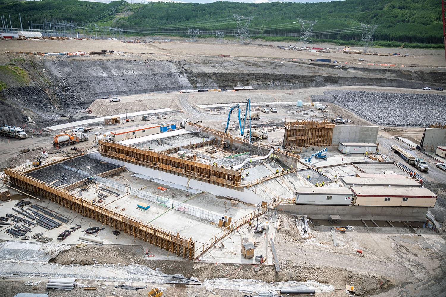
The east-end of the approach channel wall curves to divide the approach channel. Sections of the center wall are being formed and reinforcing steel placed to pour concrete. | May 2023
Caption
The east-end of the approach channel wall curves to divide the approach channel. Sections of the center wall are being formed and reinforcing steel placed to pour concrete. | May 2023
Media
Image
Media Name
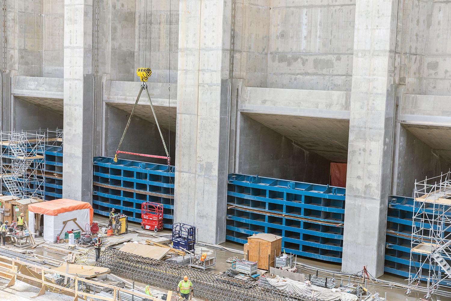
Testing and fitting tailrace gates. When the dam is operational these gates would be lowered to close the tailrace exit and stop the river from entering. The chamber below the turbine would be drained to allow for maintenance. | May 2023
Caption
Testing and fitting tailrace gates. When the dam is operational these gates would be lowered to close the tailrace exit and stop the river from entering. The chamber below the turbine would be drained to allow for maintenance. | May 2023
Media
Image
Media Name
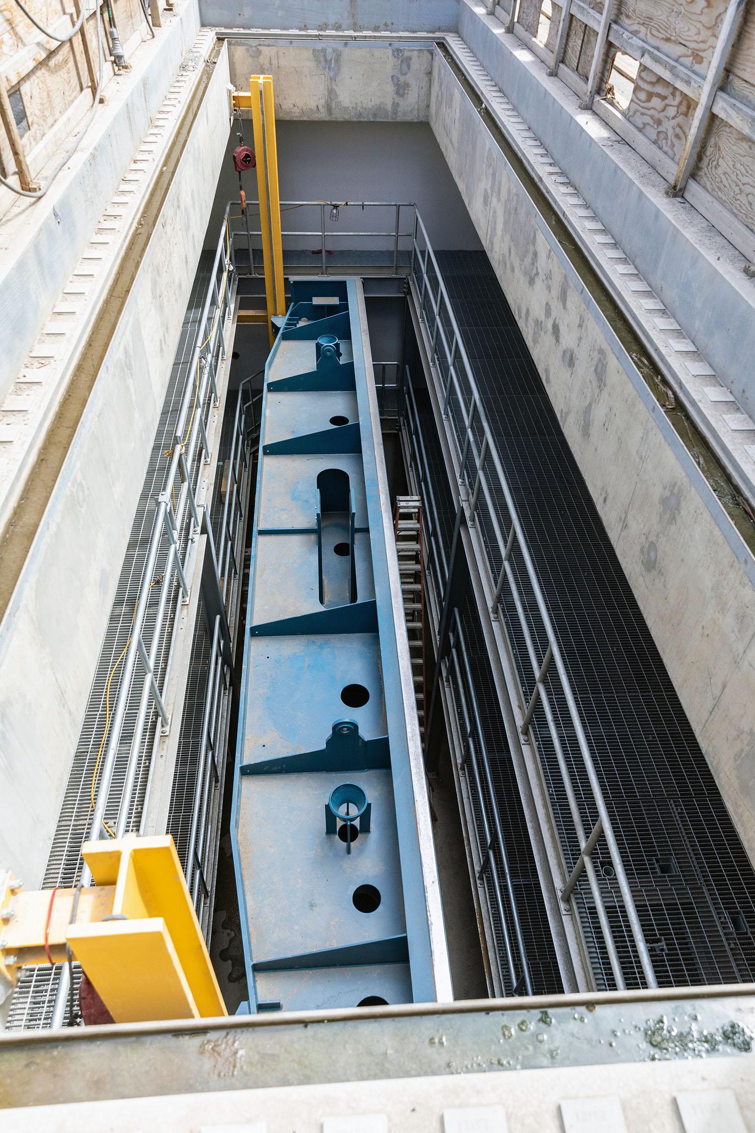
One of six intake gates inserted in the storage chamber above the gate. The gate closes the entrance to the penstock for maintenance by stopping the flow of water from the approach channel. | May 2023
Caption
One of six intake gates inserted in the storage chamber above the gate. The gate closes the entrance to the penstock for maintenance by stopping the flow of water from the approach channel. | May 2023
Media
Image
Media Name
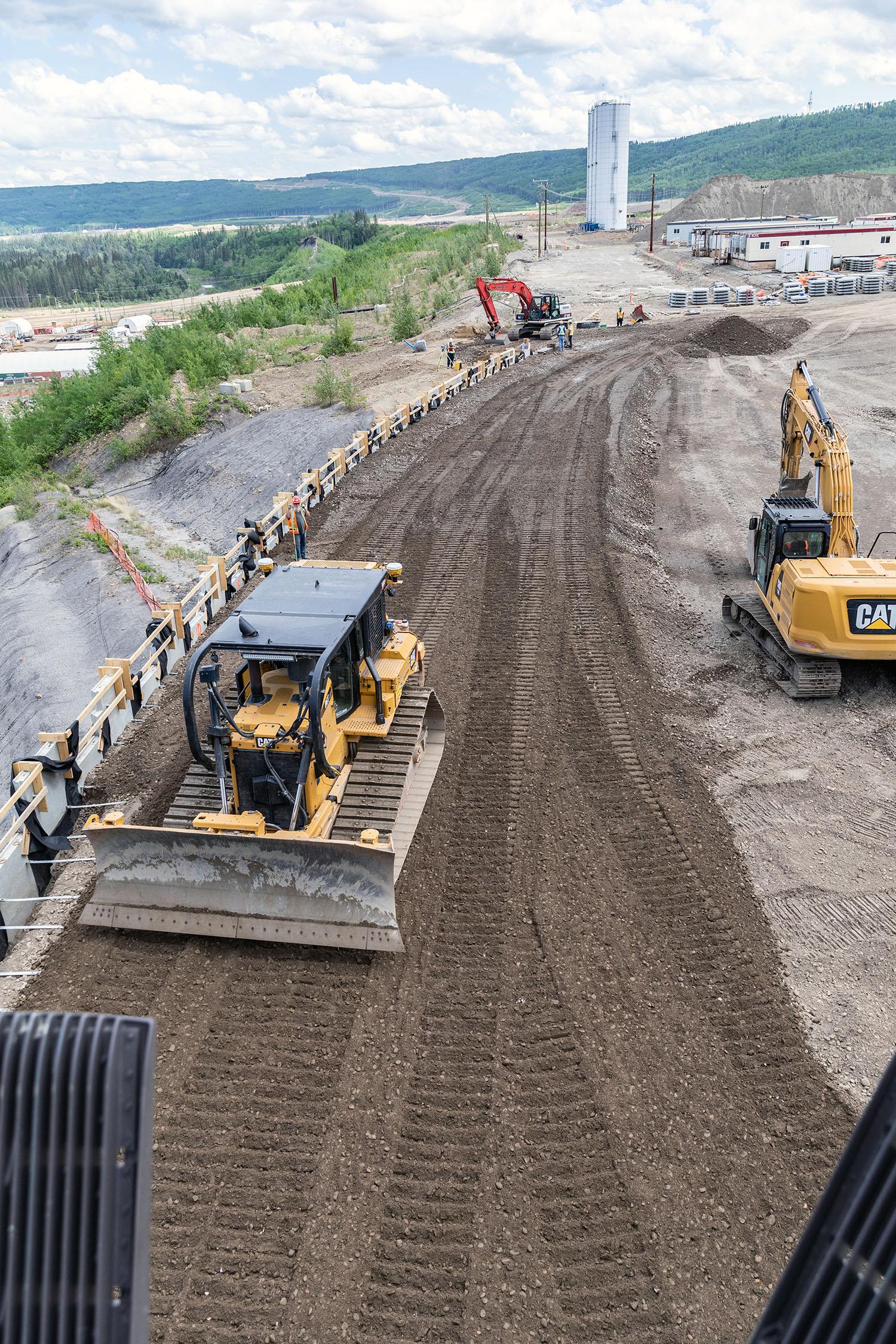
Aggregate is placed and compacted against the precast panels of the mechanical stabilized earth wall on the east side of the auxiliary spillway. | May 2023
Caption
Aggregate is placed and compacted against the precast panels of the mechanical stabilized earth wall on the east side of the auxiliary spillway. | May 2023
Media
Image
Media Name
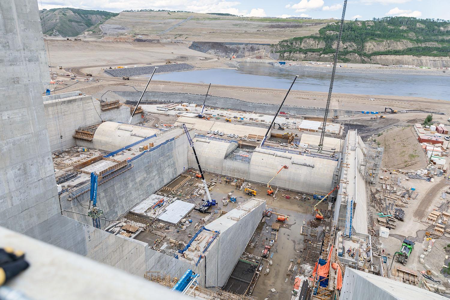
North-facing over the stilling basin of the east spillway Looking down into the east stilling basin. Forming and placing concrete for the walls, the concrete slab, and completing the weir structure. | May 2023
Caption
North-facing over the stilling basin of the east spillway Looking down into the east stilling basin. Forming and placing concrete for the walls, the concrete slab, and completing the weir structure. | May 2023
Media
Image
Media Name
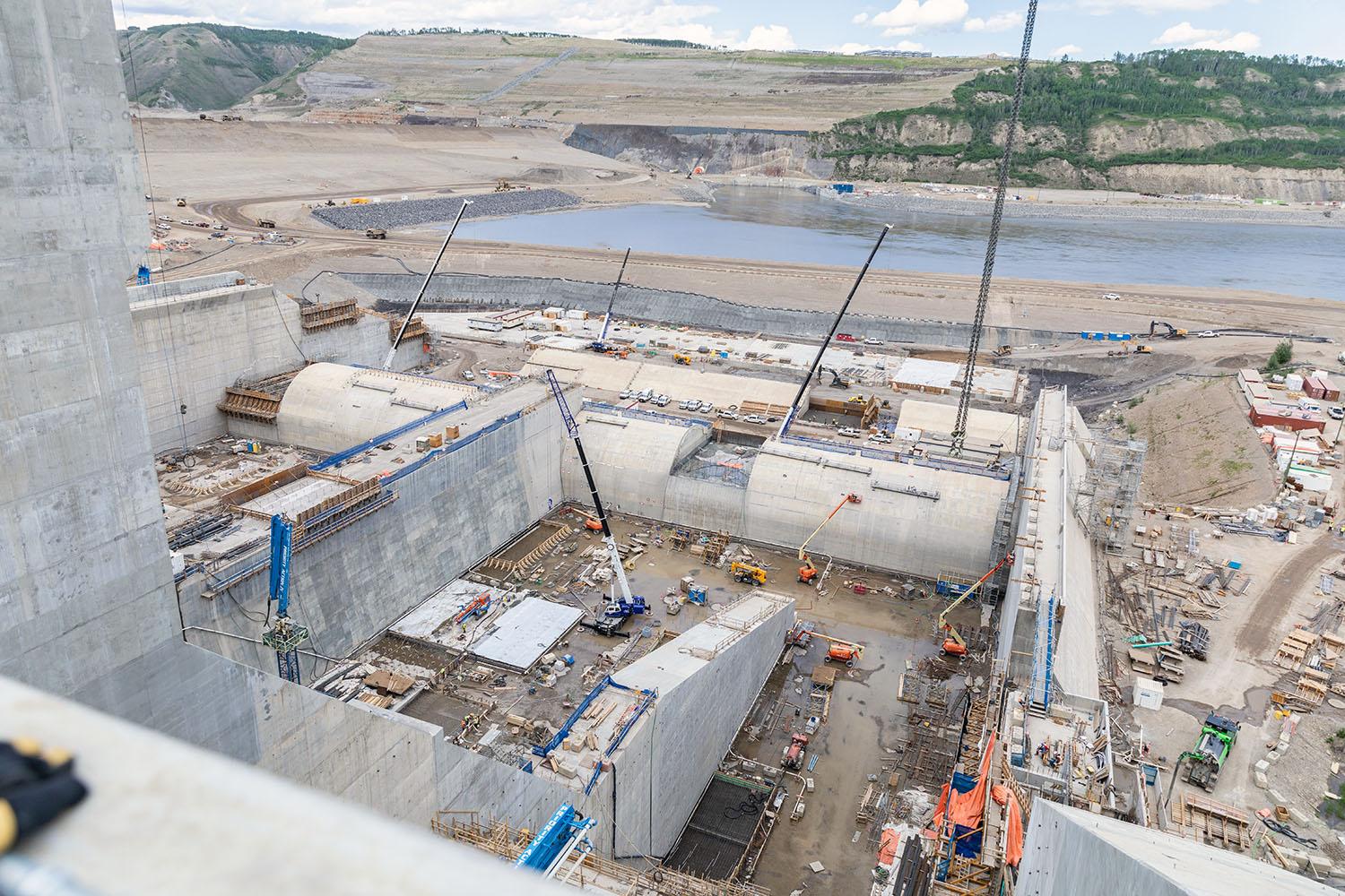
North-facing over the stilling basin of the east spillway Looking down into the east stilling basin. Forming and placing concrete for the walls, the concrete slab, and completing the weir structure. | May 2023
Caption
North-facing over the stilling basin of the east spillway Looking down into the east stilling basin. Forming and placing concrete for the walls, the concrete slab, and completing the weir structure. | May 2023
Media
Image
Media Name
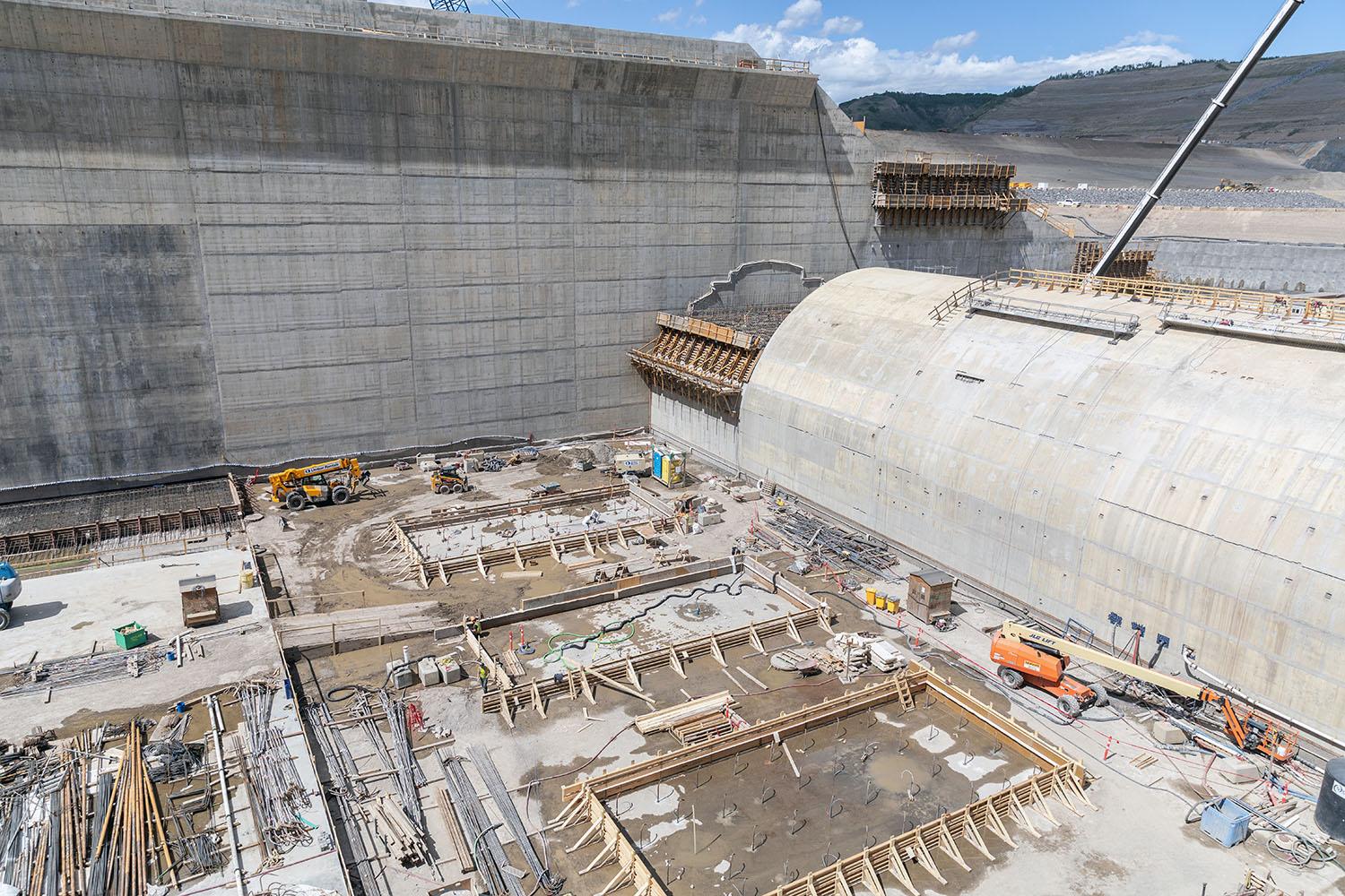
The spillway stilling basin and weir takes the energy out of water flowing from the spillway before it flows into the Peace River. The last concrete pour is underway on the last section of the weir. | May 2023
Caption
The spillway stilling basin and weir takes the energy out of water flowing from the spillway before it flows into the Peace River. The last concrete pour is underway on the last section of the weir. | May 2023
Media
Image
Media Name
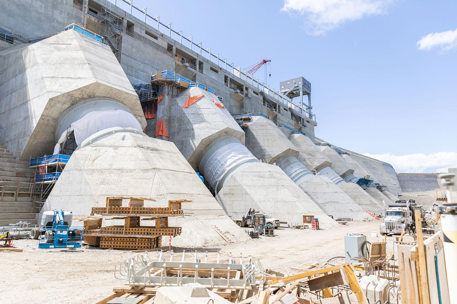
Looking west at the six penstocks where anchor bolts are being installed for the transmission tower base on penstock unit 5. | May 2023
Caption
Looking west at the six penstocks where anchor bolts are being installed for the transmission tower base on penstock unit 5. | May 2023
Media
Image
Media Name
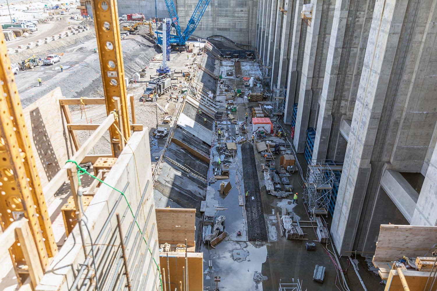
East-facing view of the foundation enhancement at the tailrace. The last section of the pile cap is being prepped for concrete placement. Crews are working on the reinforcing steel for the rock trap in front of the tailrace gates. | May 2023
Caption
East-facing view of the foundation enhancement at the tailrace. The last section of the pile cap is being prepped for
concrete placement. Crews are working on the reinforcing steel for the rock trap in front of the tailrace gates. | May 2023
concrete placement. Crews are working on the reinforcing steel for the rock trap in front of the tailrace gates. | May 2023
Media
Image
Media Name
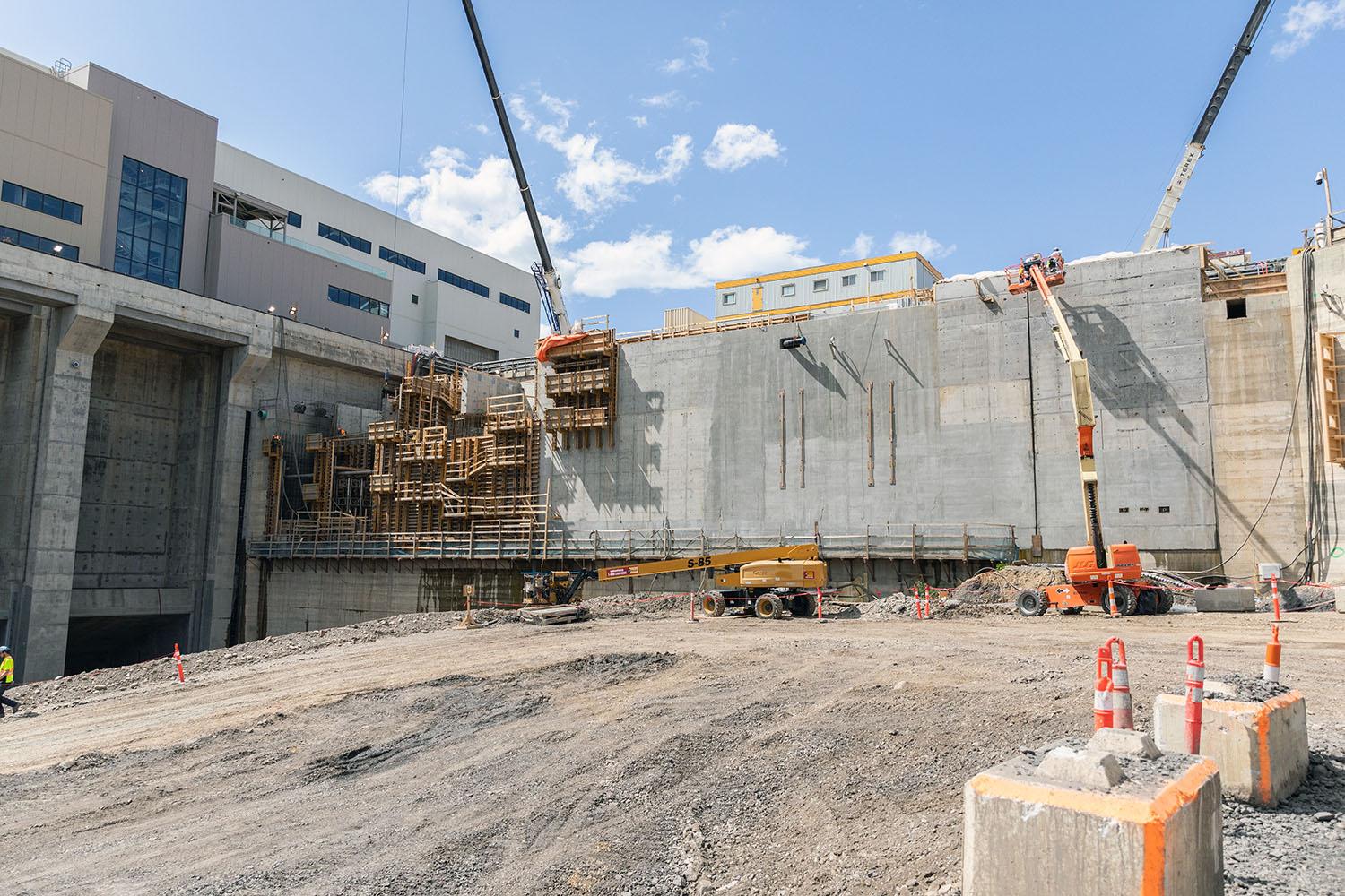
Fish that migrate up the Peace River will be sorted and tagged in the permanent upstream fish passage facility. They are placed in tanks and hauled by truck to be relocated in the reservoir on the other side of the dam. | May 2023
Caption
Fish that migrate up the Peace River will be sorted and tagged in the permanent upstream fish passage facility. They are placed in tanks and hauled by truck to be relocated in the reservoir on the other side of the dam. | May 2023
Media
Image
Media Name
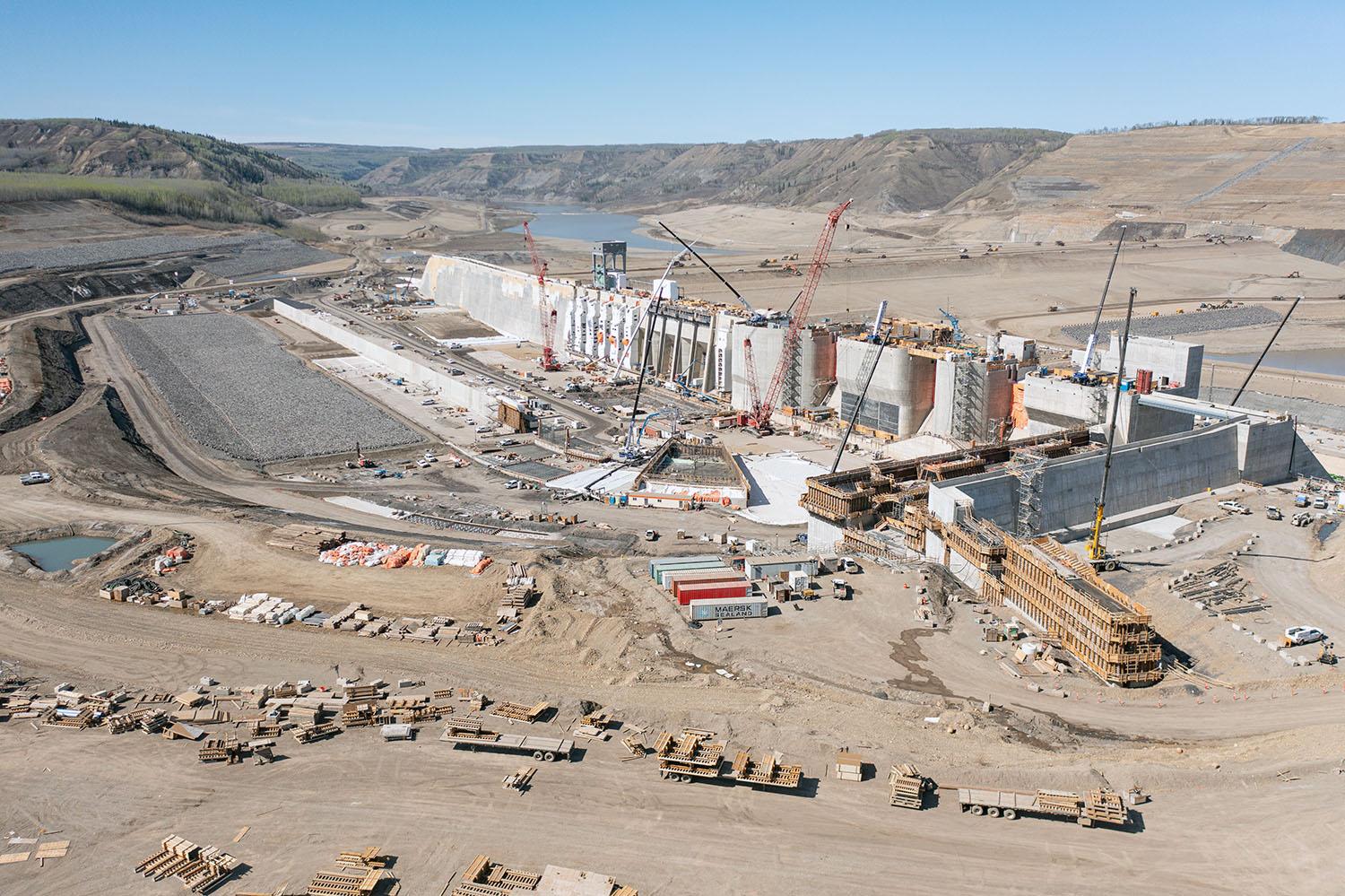
Upstream view of the approach channel, generating station, and spillways. | May 2023
Caption
Upstream view of the approach channel, generating station, and spillways. | May 2023
Media
Image
Media Name
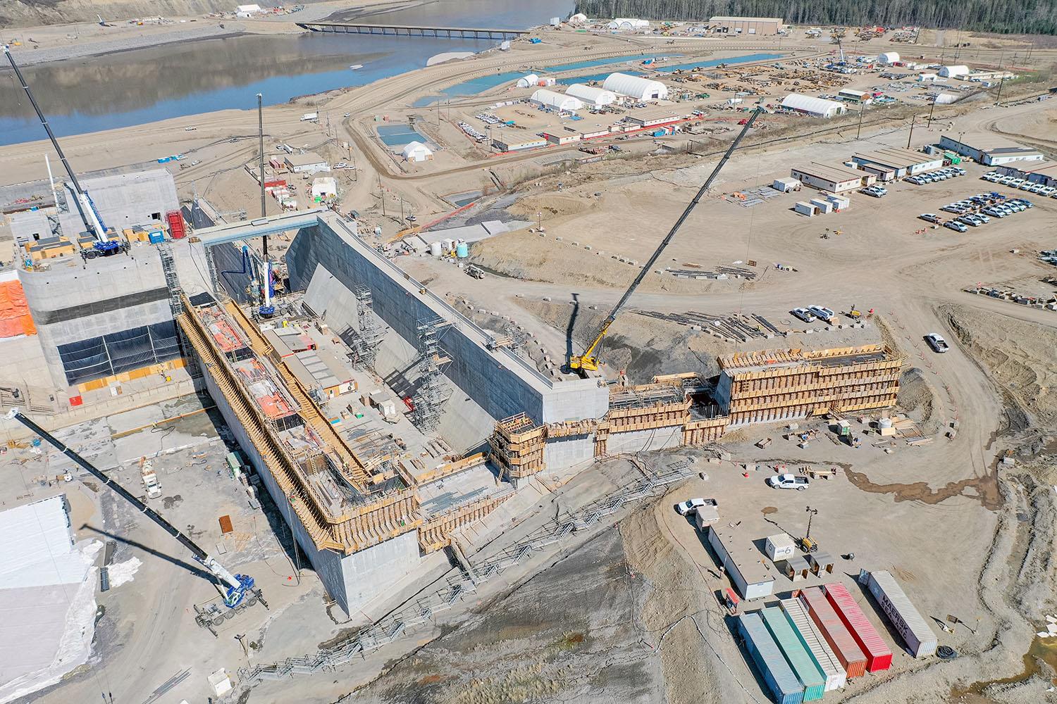
The auxiliary spillway operates without power and safely handles water that would otherwise pass through the mechanical spillways. | May 2023
Caption
The auxiliary spillway operates without power and safely handles water that would otherwise pass through the mechanical spillways. | May 2023
Media
Image
Media Name
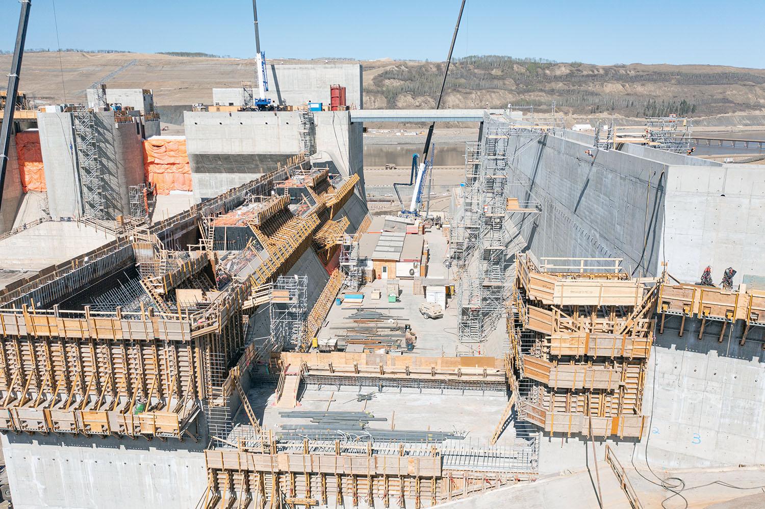
Close up look through the auxiliary spillway from the approach channel. |May 2023
Caption
Close up look through the auxiliary spillway from the approach channel. |May 2023
Media
Image
Media Name
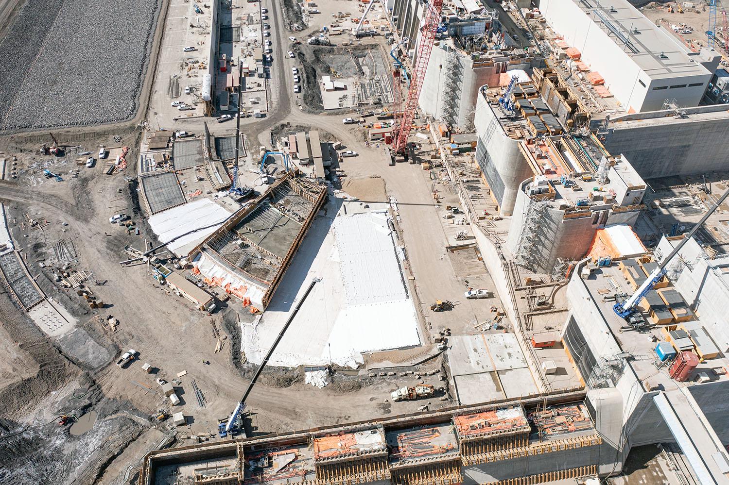
Concrete work on the centre wall of the approach channel. | May 2023
Caption
Concrete work on the centre wall of the approach channel. | May 2023
Media
Image
Media Name
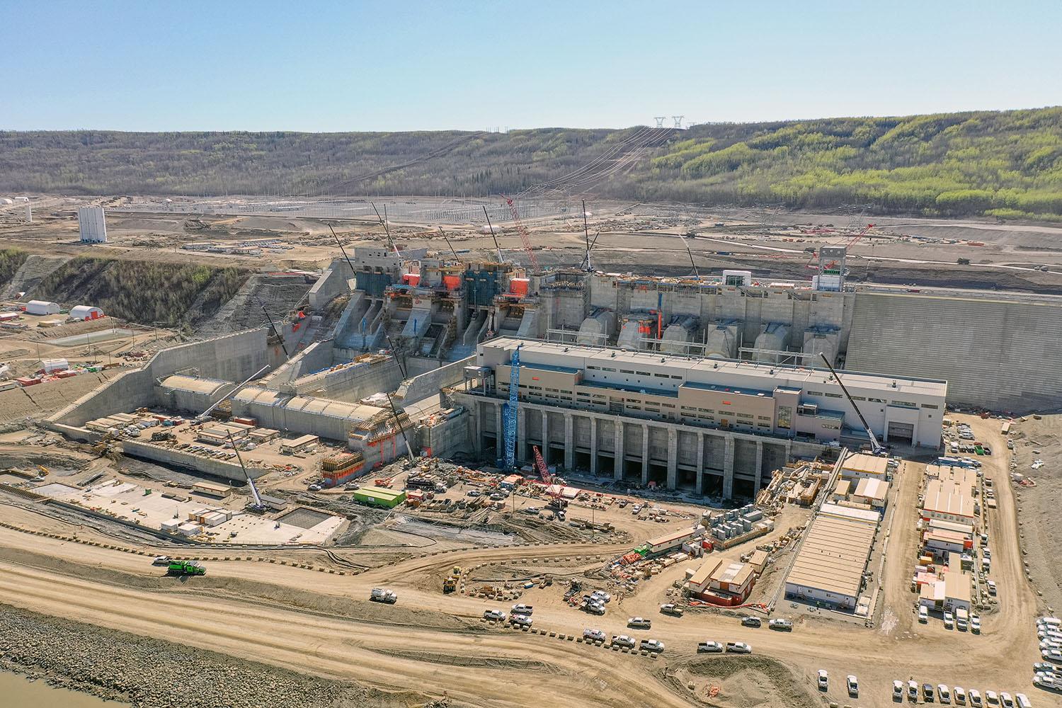
Generating station, spillways, and tailrace under construction. | May 2023
Caption
Generating station, spillways, and tailrace under construction. | May 2023
Media
Image
Media Name
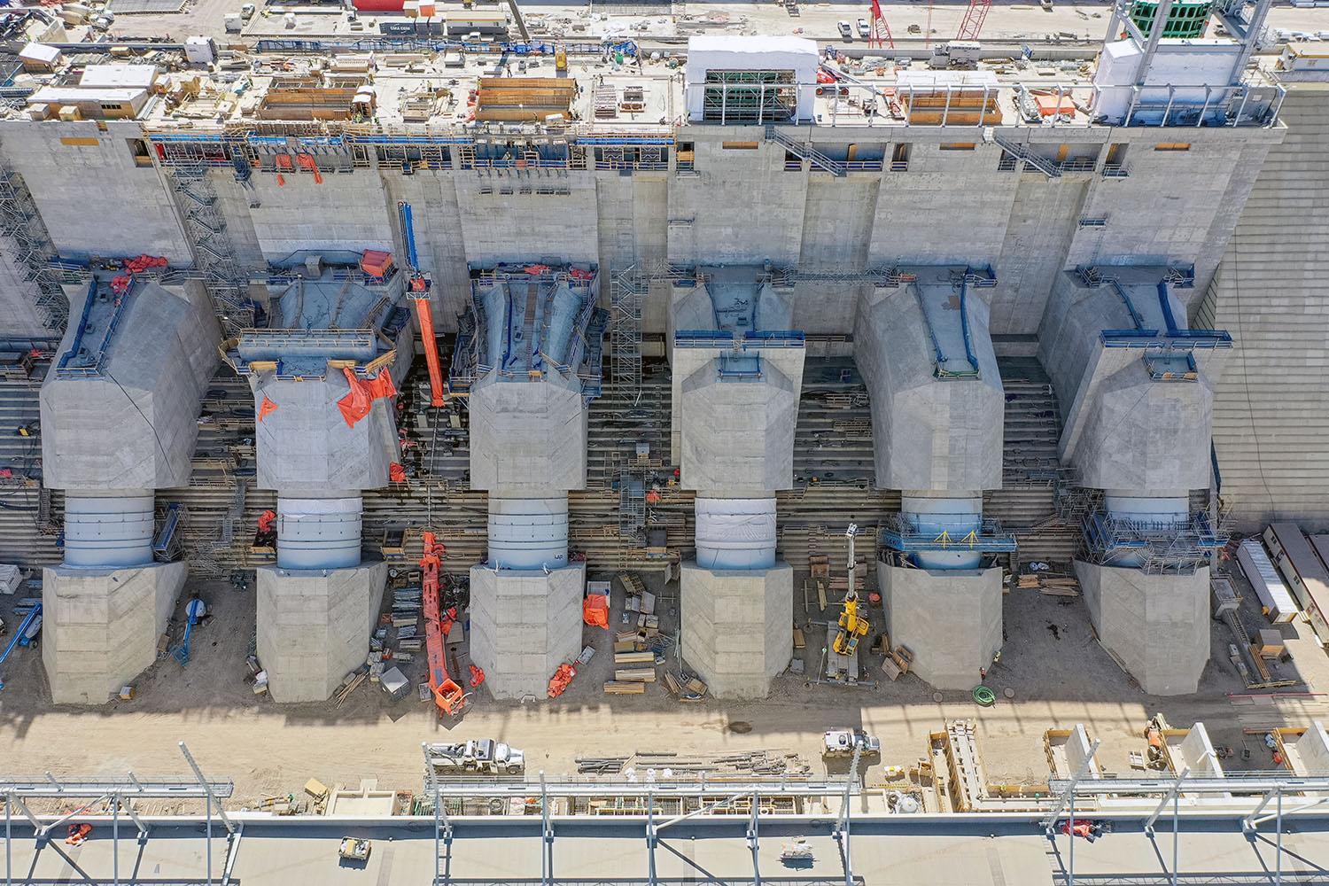
The flexible couplings are the narrower portion in the middle of each penstock. They allow the top of the penstock (embedded into the inlet) to move independently of the bottom of the penstock (embedded into the powerhouse). | May 2023
Caption
The flexible couplings are the narrower portion in the middle of each penstock. They allow the top of the penstock (embedded into the inlet) to move independently of the bottom of the penstock (embedded into the powerhouse). | May 2023
Media
Image
Media Name
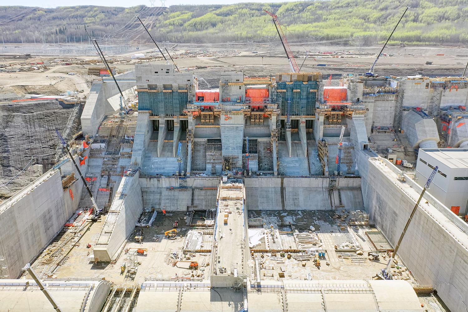
Two mechanical spillways, operated with gates, will manage flows from the reservoir. The auxiliary spillway is on the left. | May 2023
Caption
Two mechanical spillways, operated with gates, will manage flows from the reservoir. The auxiliary spillway is on the left. | May 2023
Order
8.00